Overview
We will implement dot product of two vectors of size N using Zero Knowledge Proofs (ZKP) in Circom, Halo2, . According to k12.libretexts.org, the dot product of two vectors A and B of size N is given by:
A.B = a1*b1 + a2*b2 + ... + aN*bN
- Overview
- Process Flow of a Zero Knowledge Proof
- Circom Circuit for Dotproduct of Two Vectors
- Halo2 Circuit for Dotproduct of Two Vectors
- Noir Circuit for Dotproduct of Two Vectors
Process Flow of a Zero Knowledge Proof
The below diagram describes a typical process flow in creating a Zero Knowledge Proof system. 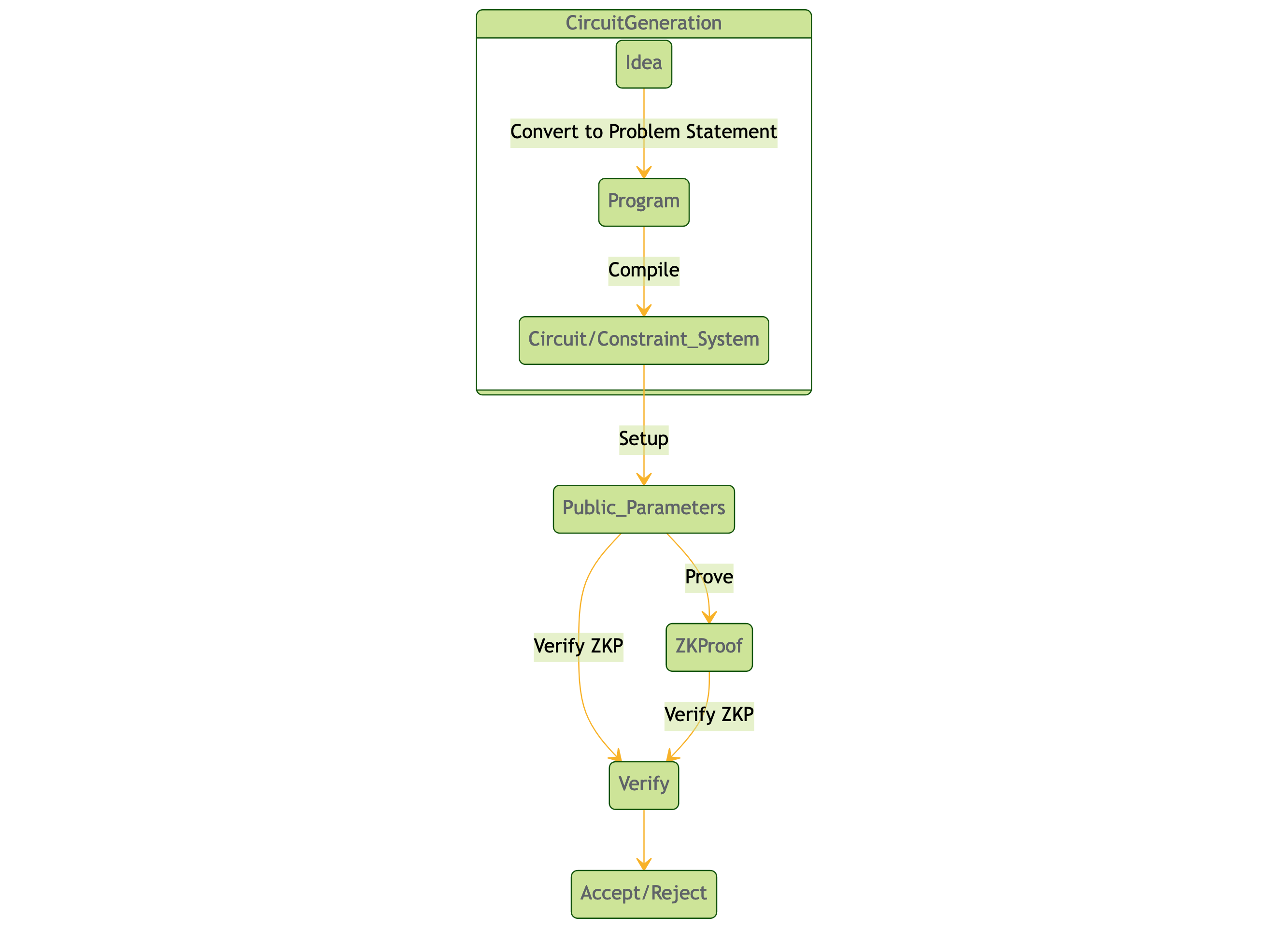
To create zero-knowledge proofs and circuits using different libraries like Circom, Noir, and Halo2, follow these steps:
- Define the problem: Identify the problem you want to prove using zero-knowledge proofs. For instance, prove that you are a member of top 100 Uniswap liquidity provider without revealing any additional information or that you identified a critical bug in a smart contract without revealing any additional information.
- Choose the appropriate ZKP library: Select the library that suits your needs, such as Circom, Noir, or Halo2 or others. Each library has its own set of features and trade-offs:
- Circom: A domain-specific language (DSL) designed for creating circuits in a simple and intuitive way. It’s useful for creating zk-SNARK circuits. For more details on Circom, visit the official documentation.
- Noir: A high-level, general-purpose language for creating zero-knowledge proofs. It’s easy to understand and has a growing ecosystem. For more details on Noir, visit the official documentation.
- Halo2: A library for constructing zk-SNARKs without a trusted setup, providing a more secure and efficient alternative to some other libraries. For more details on Halo2, visit the official documentation.
- Create the circuit: Design the circuit that represents the problem using the chosen library. This involves defining the inputs, outputs, and constraints that must be satisfied for the proof to be valid.
- Generate the proof: Using the library’s tools, generate the zero-knowledge proof that demonstrates the statement is true without revealing any additional information.
- Verify the proof: Implement the verification process to ensure that the proof is valid and the statement is true, without learning any additional information.
Circom Circuit for Dotproduct of Two Vectors
In this example we will investigate how to write a Circom circuit for the dotproduct of two vectors, create a Zero Knowledge Proof and verify the proof withoit revealing any additional information.
Circom Setup and Installation
The complete and latest documentation for installing the Circom ecosystem can be found here. The older versions of Circom can be also installed from the old circom repository.
Circom Install dependencies
The Circom compiler is written in Rust. To have Rust available in your system, you can install rustup. If you’re using Linux or macOS, open a terminal and enter the following command:
curl --proto '=https' --tlsv1.2 https://sh.rustup.rs -sSf | sh
You also need the latest version of Node.js (or yarn). You can install them from here.
Install Circom
First, clone the circom repository:
git clone https://github.com/iden3/circom.git
Enter the circom directory and use the cargo build to compile:
cargo build --release
The installation takes around 3 minutes to be completed. When the command successfully finishes, it generates the circom binary in the directory target/release. You can install this binary as follows:
cargo install --path circom
The previous command will install the circom binary in the directory $HOME/.cargo/bin.
Install Snarkjs
You can install snarkjs with the following command:
npm install -g snarkjs
Implementing Circom Circuit for the Dotproduct of Two Vectors
To implement the dotproduct of two vectors in Circom, we can follow the steps below:
- Define the two vectors
AandBof sizeN. - Define a variable to store the dot product.
- Calculate the dot product by multiplying the corresponding components of
AandBand adding them together. - Output the dot product.
Here’s what the code would look like in Circom:
template DotProduct(N: number) {
    signal A[N];
    signal B[N];
    signal result;

    component multiply[N];
    component add[N-1];

    for (i = 0; i < N; i++) {
        multiply[i] A[i] * B[i] -> add[i];
    }

    for (i = 0; i < N-1; i++) {
        add[i] + add[i+1] -> add[i+1];
    }

    add[N-2] -> result;
}
In the above code, we define two input signals A and B of size N, which represent the two vectors. We also define an output signal result, which will store the dot product.
We then define two components, multiply and add. The multiply component multiplies the corresponding components of A and B, while the add component adds them together. We use a loop to connect the outputs of the multiply components to the inputs of the add components. We also use a loop to connect the outputs of the add components to each other, until we reach the final output signal result.
To use this template, we can simply instantiate it and provide values for the A and B signals:
template Main() {
    signal A[4] = [3, -5, 4, 2];
    signal B[4] = [2, 6, 5, 1];
    signal result;

    DotProduct(4)()
        .A(A)
        .B(B)
        .result(result);

    print(result);
}
In the above code, we define the two input signals A and B of size 4, and an output signal result. We then instantiate the DotProduct template with a size of 4, and connect its A and B signals to the corresponding input signals. We also connect its result signal to our output signal. Finally, we print the result signal.
Halo2 Circuit for Dotproduct of Two Vectors
In this example we will investigate how to write a Halo2 circuit for the dotproduct of two vectors, create a Zero Knowledge Proof and verify the proof without revealing any additional information.
Halo2 Setup and Installation
Halo2 requires the latest Rust. You can find more about developing using Halo2 at the official halo2 documentation.
Implementing Halo2 Circuit for the Dotproduct of Two Vectors
To implement the dotproduct of two vectors in Halo2, we first need to define our circuit in Halo2. Here is the code for this:
use halo2::{
    circuit::{Layouter, SimpleFloorPlanner},
    plonk::{Circuit, ConstraintSystem, Error},
    poly::Rotation,
};

// Define the circuit struct
#[derive(Debug)]
struct DotProduct<'a> {
    a: &'a [u64],
    b: &'a [u64],
    result: &'a mut [u64],
}

// Implement the Circuit trait for our circuit
impl<'a> Circuit<SimpleFloorPlanner> for DotProduct<'a> {
    type Config = ();
    type FloorPlanner = SimpleFloorPlanner;

    fn without_witnesses(&self) -> Self {
        DotProduct {
            a: self.a,
            b: self.b,
            result: &mut [0; N],
        }
    }

    fn configure(
        _config: Self::Config,
        meta: &mut ConstraintSystem<SimpleFloorPlanner>,
    ) -> Result<(), Error> {
        // Define the input signals A and B
        let a = meta.advice_column();
        let b = meta.advice_column();

        // Define the intermediate signals for multiplication
        let mul = (0..N)
            .map(|_| meta.advice_column())
            .collect::<Vec<_>>();

        // Define the intermediate signals for addition
        let add = (0..N - 1)
            .map(|_| meta.advice_column())
            .collect::<Vec<_>>();

        // Define the output signal result
        let result = meta.advice_column();

        // Constrain the input signals to the values provided
        for (i, &value) in self.a.iter().enumerate() {
            meta.enable_constant(a[i], value.into())?;
        }
        for (i, &value) in self.b.iter().enumerate() {
            meta.enable_constant(b[i], value.into())?;
        }

        // Constrain the multiplication signals to the product
        // of the corresponding components of A and B
        for i in 0..N {
            meta.multiply(
                Rotation::prev(),
                &[a[i], b[i]],
                mul[i],
            )?;
        }

        // Constrain the addition signals to the sum of the
        // corresponding multiplication signals
        for i in 0..N - 1 {
            meta.add(
                Rotation::cur(),
                &[mul[i], mul[i + 1]],
                add[i],
            )?;
        }

        // Constrain the output signal to the last addition signal
        meta.copy(
            Rotation::cur(),
            add[N - 2],
            result,
        )?;

        // Constrain the output signal to the value provided
        for (i, &value) in self.result.iter().enumerate() {
            meta.constrain_equal(result, value.into())?;
        }

        Ok(())
    }
}
In this code, we define our circuit struct DotProduct, which contains the input signals a and b, and an output signal result. We also implement the Circuit trait for our circuit, which defines how the circuit should be constructed and constrained.
We define the input signals a and b using meta.advice_column(), which creates a new advice column in the circuit. We also define the intermediate signals mul and add, which will be used to perform the multiplication and addition operations. Finally, we define the output signal result.
We constrain the input signals to the values provided using meta.enable_constant(), which constrains the advice column to a constant value. We then constrain the multiplication signals using meta.multiply(), which constrains the product of the corresponding components of a and b to the corresponding multiplication signal. We then constrain the addition signals using meta.add(), which constrains the sum of the corresponding multiplication signals to the corresponding addition signal. Finally, we constrain the output signal to the last addition signal using meta.copy(), and constrain it to the value provided using meta.constrain_equal().
To use this circuit, we can instantiate it with the values for a and b, and an empty vector for result. We can then create a proof using ` Prover::prove() , and verify the proof using Verifier::verify() `. Here’s an example:
use halo2::{
    dev::MockProver,
    plonk::{Circuit, ConstraintSystem, Verifier},
};

// Define the size of our vectors
const N: usize = 4;

// Define our main function
fn main() {
    // Define the input signals A and B
    let a = [3, 5, 4, 2];
    let b = [2, 6, 5, 1];

    // Define the output signal result
    let mut result = [0; N];

    // Instantiate the circuit
    let circuit = DotProduct {
        a: &a,
        b: &b,
        result: &mut result,
    };

    // Create a proof
    let prover = MockProver::run(N, &circuit, vec![]).unwrap();
    let proof = prover.proof;

    // Verify the proof
    let verifier = Verifier::new(N, &circuit, &proof).unwrap();
    assert!(verifier.verify().is_ok());

    // Print the result
    println!("{:?}", result);
}
In this code, we define the input signals a and b and the output signal result. We then instantiate the DotProduct circuit with these values. We create a proof using MockProver::run(), which simulates the circuit execution and generates a proof. We then verify the proof using Verifier::new() and verify(). Finally, we print the result.
Note that in this example, we use MockProver to generate a proof and verify it. In a real-world application, we would use a trusted setup to generate the proving and verifying keys, and use those keys to generate and verify proofs. We would also need to ensure that the inputs and outputs of the circuit are properly encrypted and decrypted to prevent information leakage. However, these details are beyond the scope of this example.
What is a trusted setup and why is it necessary in a real-world application?
A trusted setup is a process used in some zero-knowledge proof systems, including Halo2, to generate the proving and verifying keys that are used to generate and verify proofs. The trusted setup involves a group of trusted individuals or entities who collectively generate and destroy a secret value that is used to generate the keys. The secret value is destroyed after the keys are generated, so that no one can learn it and use it to generate fake proofs.
The trusted setup is necessary in a real-world application because it ensures that the proving and verifying keys are generated in a way that is secure and unbiased. Without a trusted setup, an attacker could potentially generate their own keys and use them to generate fake proofs that are accepted by the system. The trusted setup ensures that the keys are generated in a way that is independent of the attacker, and that the attacker cannot learn the secret value used to generate the keys.
In Halo2, the trusted setup involves generating a random permutation of the circuit’s columns, and using this permutation to generate the keys. The permutation is generated using a multiparty computation protocol, where each participant contributes a random value that is combined to generate the final permutation. The permutation ensures that the circuit’s columns are mixed together in a way that prevents an attacker from learning anything about the circuit by observing the keys.
Once the trusted setup is complete, the proving and verifying keys are distributed to the users of the system, who can use them to generate and verify proofs. The users do not need to trust each other or the system, because the keys were generated in a way that is secure and unbiased. However, the users must ensure that the inputs and outputs of the circuit are properly encrypted and decrypted, to prevent information leakage.
In summary, a trusted setup is a process used to generate the proving and verifying keys for a zero-knowledge proof system, and is necessary in a real-world application to ensure that the keys are generated in a way that is secure and unbiased.
Noir Circuit for Dotproduct of Two Vectors
In this example we will investigate how to write a Noir circuit for the dotproduct of two vectors, create a Zero Knowledge Proof and verify the proof without revealing any additional information.
For more details about Noir programming language, visit the official documentation.
Installing Noir
Noir is a Rust based language. You can visit the official documentation for installation instructions.
Implementing Noir Circuit for the Dotproduct of Two Vectors
To implement the dotproduct of two vectors in Noir, we first need to define our circuit in Noir. Here is the code for this:
// Noir does not have a built-in dot product function, so we create one
fn dot_product(vect_A: [field], vect_B: [field]) -> field {
    let mut result: field = 0;
    let N = vect_A.len();

    for i in 0..N {
        result += vect_A[i] * vect_B[i];
    }

    return result;
}

// Example usage
fn main() {
    let vect_A: [field] = [1, 2, 3, 4];
    let vect_B: [field] = [5, 6, 7, 8];

    let result: field = dot_product(vect_A, vect_B);

    // The result should be 70 (1*5 + 2*6 + 3*7 + 4*8)
    assert_eq!(result, 70);
}
- The
dot_productfunction is defined with two input parameters,vect_Aandvect_B, both of which are arrays of fields (a field is a type in Noir representing a finite field element). The function returns a field. - Inside the
dot_productfunction, a mutable variable result is initialized with a value of0, and the length ofvect_Ais stored in the variableN. - A for loop iterates through the indices of both input arrays, from
0toN-1. In each iteration, the corresponding elements of the two arrays are multiplied and added to theresult. - The
resultis returned as the output of thedot_productfunction. - The main function demonstrates how to use the
dot_productfunction. Two arrays,vect_Aandvect_B, are defined, and their dot product is calculated using thedot_productfunction. - Finally, an assertion checks that the
resultis equal to70, which is the expected dot product value(15 + 26 + 37 + 48).
The following steps will build the ZKP program and creates proofs and verifies the proof without any additional information.
- Build:
nargo check - Prove: Enter the inputs in
Prover.tomland runnargo prove p -v. Or,nargo prove --show-output pto show println logs. - Verify:
nargo verify p